
A gyroscope is a device for measuring or maintaining orientation, based on the principles of angular momentum[1][2]. The device is a spinning wheel or disk whose axle is free to take any orientation. This orientation changes much less in response to a given external torque than it would without the large angular momentum associated with the gyroscope's high rate of spin. Since external torque is minimized by mounting the device in gimbals, its orientation remains nearly fixed, regardless of any motion of the platform on which it is mounted.
Description and diagram

Within mechanical systems or devices, a conventional gyroscope is a mechanism comprising a rotor journaled to spin about one axis, the journals of the rotor being mounted in an inner gimbal or ring, the inner gimbal being journaled for oscillation in an outer gimbal which in turn is journaled for oscillation relative to a support. The outer gimbal or ring is mounted so as to pivot about an axis in its own plane determined by the support. The outer gimbal possesses one degree of rotational freedom and its axis possesses none. The inner gimbal is mounted in the outer gimbal so as to pivot about an axis in its own plane, which axis is always perpendicular to the pivotal axis of the outer gimbal.
The axle of the spinning wheel defines the spin axis. The inner gimbal possesses two degrees of rotational freedom and its axis possesses one. The rotor is journaled to spin about an axis which is always perpendicular to the axis of the inner gimbal. So, the rotor possesses three degrees of rotational freedom and its axis possesses two. The wheel responds to a force applied about the input axis by a reaction force about the output axis.
The behaviour of a gyroscope can be most easily appreciated by consideration of the front wheel of a bicycle. If the wheel is leaned away from the vertical so that the top of the wheel moves to the left, the forward rim of the wheel also turns to the left. In other words, rotation on one axis of the turning wheel produces rotation of the third axis.
A gyroscope flywheel will roll or resist about the output axis depending upon whether the output gimbals are of a free- or fixed- configuration. Examples of some free-output-gimbal devices would be the attitude reference gyroscopes used to sense or measure the pitch, roll and yaw attitude angles in a spacecraft or aircraft.

The center of gravity of the rotor can be in a fixed position. The rotor simultaneously spins about one axis and is capable of oscillating about the two other axes, and thus, except for its inherent resistance due to rotor spin, it is free to turn in any direction about the fixed point. Some gyroscopes have mechanical equivalents substituted for one or more of the elements, e.g., the spinning rotor may be suspended in a fluid, instead of being pivotally mounted in gimbals. A control moment gyroscope (CMG) is an example of a fixed-output-gimbal device that is used on spacecraft to hold or maintain a desired attitude angle or pointing direction using the gyroscopic resistance force.
In some special cases, the outer gimbal (or its equivalent) may be omitted so that the rotor has only two degrees of freedom. In other cases, the center of gravity of the rotor may be offset from the axis of oscillation, and thus the center of gravity of the rotor and the center of suspension of the rotor may not coincide.
History

The earliest known gyroscope was made by Johann Bohnenberger in 1817, although he called it simply the 'Machine'. The French mathematician Pierre-Simon Laplace, working at the École Polytechnique in Paris, recommended the machine for use as a teaching aid, and thus it came to the attention of Léon Foucault. [3] In 1852, Foucault used it in an experiment involving the rotation of the Earth. It was Foucault who gave the device its modern name, in an experiment to see (Greek skopeein, to see) the Earth's rotation (Greek gyros, circle or rotation), although the experiment was unsuccessful due to friction, which effectively limited each trial to 8 to 10 minutes, too short a time to observe significant movement.
In the 1860s, electric motors made the concept feasible, leading to the first prototype gyrocompasses; the first functional marine gyrocompass was developed between 1905 and 1908 by German inventor Hermann Anschütz-Kaempfe. The American Elmer Sperry followed with his own design in 1910, and other nations soon realized the military importance of the invention— in an age in which naval might was the most significant measure of military power— and created their own gyroscope industries. The Sperry Gyroscope Company quickly expanded to provide aircraft and naval stabilizers as well, and other gyroscope developers followed suit.[4]
In 1917, the Chandler Company of Indianapolis, Indiana created the "Chandler gyroscope", a toy gyroscope with a pull string and pedestal. It has been in continuous production ever since and is considered a classic American toy.
MEMS gyroscopes take the idea of the Foucault pendulum and use a vibrating element, known as a MEMS (Micro Electro-Mechanical System). The MEMS based gyro was initially made practical and produceable by Systron Donner Inertial (SDI). Today, SDI is a large manufacturer of MEMS gyroscopes.
In the first several decades of the 20th century, other inventors attempted (unsuccessfully) to use gyroscopes as the basis for early black box navigational systems by creating a stable platform from which accurate acceleration measurements could be performed (in order to bypass the need for star sightings to calculate position). Similar principles were later employed in the development of inertial guidance systems for ballistic missiles.[5]
Properties

A gyroscope exhibits a number of behaviours including precession and nutation. Gyroscopes can be used to construct gyrocompasses which complement or replace magnetic compasses (in ships, aircraft and spacecraft, vehicles in general), to assist in stability (bicycle, Hubble Space Telescope, ships, vehicles in general) or be used as part of an inertial guidance system. Gyroscopic effects are used in toys like yo-yos and Powerballs. Many other rotating devices, such as flywheels, behave gyroscopically although the gyroscopic effect is not used.
The fundamental equation describing the behavior of the gyroscope is:
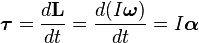
where the vectors  and
and  are, respectively, the torque on the gyroscope and its angular momentum, the scalar
  is its moment of inertia, the vector
  is its angular velocity, and the vector
  is its angular acceleration.
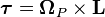
It follows from this that a torque applied perpendicular to the axis of rotation, and therefore perpendicular to , results in a rotation about an axis perpendicular to both and . This motion is called precession. The angular velocity of precession  is given by the cross product:

Precession can be demonstrated by placing a spinning gyroscope with its axis horizontal and supported loosely (frictionless toward precession) at one end. Instead of falling, as might be expected, the gyroscope appears to defy gravity by remaining with its axis horizontal, when the other end of the axis is left unsupported and the free end of the axis slowly describes a circle in a horizontal plane, the resulting precession turning. This effect is explained by the above equations. The torque on the gyroscope is supplied by a couple of forces: gravity acting downwards on the device's centre of mass, and an equal force acting upwards to support one end of the device. The rotation resulting from this torque is not downwards, as might be intuitively expected, causing the device to fall, but perpendicular to both the gravitational torque (horizontal and perpendicular to the axis of rotation) and the axis of rotation (horizontal and outwards from the point of support), i.e. about a vertical axis, causing the device to rotate slowly about the supporting point.
As the second equation shows, under a constant torque, the gyroscope's speed of precession is inversely proportional to its angular momentum. This means that, for instance, if friction causes the gyroscope's spin to slow down, the rate of precession increases. This continues until the device is unable to rotate fast enough to support its own weight, when it stops precessing and falls off its support, mostly because friction against precession cause another precession that goes to cause the fall.
By convention, these three vectors, torque, spin, and precession, are all oriented with respect to each other according to the right-hand rule.
To easily ascertain the direction of gyro effect, simply remember that a rolling wheel tends, when entering a corner, to turn over to the inside.
Gyrostat
A gyrostat is a variant of the gyroscope. The first gyrostat was designed by Lord Kelvin to illustrate the more complicated state of motion of a spinning body when free to wander about on a horizontal plane, like a top spun on the pavement, or a hoop or bicycle on the road. It consists of a massive flywheel concealed in a solid casing. Its behaviour on a table, or with various modes of suspension or support, serves to illustrate the curious reversal of the ordinary laws of static equilibrium due to the gyrostatic behaviour of the interior invisible flywheel when rotated rapidly.
U.S. Patents
In the USPTO classification scheme, the generic locus for gyroscope patents is Class 74, Machine element or mechanism, and Subclass 5R. Every rotating body has gyroscopic action, but such devices are not included unless at least one axis of oscillation is present. The combinations of gyroscopes with other devices are placed in subclass 5.22.
- Numbers
- U.S. Patent 839,161, "Steering apparatus for automobile torpedoes", .
- U.S. Patent 795,045, "Gyroscopic control apparatus", .
- U.S. Patent 785,587, "Mechanical speed governor".
- U.S. Patent 785,425, "Steering mechanism for torpedoes".
- U.S. Patent 751,888, "Governing mechanism for turbines".
- U.S. Patent 738,823, "Electrical apparatus".
- U.S. Patent 730,613, "Meter".
- U.S. Patent 662,484, "Electric top for gyroscopes".
- U.S. Patent 648,878, "Gyroscope for torpedo steering mechanism".
- U.S. Patent 642,704, "Roller bearing car wheel".
- U.S. Patent 484,960, "Gyroscopic top".
- U.S. Patent 461,948, "Gyroscope or revolving toy".
- U.S. Patent 365,530, "Lumber cart".
- U.S. Patent 312,692, "Vehicle wheel".
- U.S. Patent 220,867, "Engine-governor and speed-regulator".
- U.S. Patent 162,446, "Governor for steam engine".
- U.S. Patent 34,298, "Levelling instrument".
- Reissued
- U.S. Patent RE024,880, "Rate Gyroscope with torsional suspension"
See also
- Aerotrim
- Control Moment Gyroscope
- Euler angles
- Eric Laithwaite
- Fibre optic gyroscope
- Gimbal
- Gimbal lock
- Gyro Monorail
- Gyrocar
- Gyrocompass
- Gyroscopic exercise tool
- Momentum wheel
- Precession
- Quantum gyroscope
- Rate integrating gyroscope
- Rifling
- Ring laser gyroscope
- Segway
- Anti rolling gyro - Ship gyroscopic roll stabilisers.
- Top
- Vibrating structure gyroscope
References
- ^ "Gyroscope" by Sándor Kabai, The Wolfram Demonstrations Project.
- ^ "Total Angular Momentum", ScienceWorld
- ^ Wagner JF, "The Machine of Bohnenberger", The Institute of Navigation [1]
- ^ MacKenzie, Donald. Inventing Accuracy: A Historical Sociology of Nuclear Missile Guidance. Cambridge: MIT Press, 1990. pp 31-40. ISBN 0-262-13258-3
- ^ MacKenzie, pp 40-42.
External articles and further readings
- Books
- Felix Klein and Arnold Sommerfeld, "Über die Theorie des Kreisels" (Tr., About the theory of the gyroscope). Leipzig, Berlin, B.G. Teubner, 1898-1914. 4 v. illus. 25 cm.
- Audin, M. Spinning Tops: A Course on Integrable Systems. New York: Cambridge University Press, 1996.
- Websites
- Technical White Papers on Gyroscopes
- Description of the Systron Donner Inertial MEMS gyroscope
- The Precession and Nutation of a Gyroscope
- Everything you needed to know about gyroscopes
- Project in which gyroscopes are used to drive a robotic arm
- Manufacturers that use the force produced by twin gyroscopes to stabilise motor yachts and ships
- Examples of gyroscopes
- Papers
- Theory and Design of Micromechanical Vibratory Gyroscopes Vladislav Apostolyuk
- Lectures
- The Royal Institution’s 1974-75 Christmas Lecture Professor Eric Laithwaite
No comments:
Post a Comment