Aeronautical chart
From Wikipedia, the free encyclopedia
Jump to: navigation, search
An aeronautical chart is a map designed to assist in navigation of aircraft, much as nautical charts do for watercraft, or a roadmap for drivers. Using these charts and other tools pilots are able to determine their position, safe altitude, best route to a destination, navigation aids along the way, alternative landing areas in case of an in-flight emergency, and other useful information such as radio frequencies and airspace boundaries. There are charts for all land masses on Earth, and long-distance charts for trans-oceanic travel.
Specific charts are used for each phase of a flight and may vary from a map of a particular airport facility to an overview of the instrument routes covering an entire continent (e.g., global navigation charts), and many types in between.
Charts for visual flight rules (VFR)
Under "visual flight rules", pilots are expected to see and avoid dangers along the way (obstacles, other aircraft, bad weather, etc), and to use pilotage and other means for navigating. VFR charts include a large amount of information describing the local topography, not the least of which is the elevation. Standardized symbols are used for indication of land and water features such as mountains, shorelines and rivers. Roads, towns and other identifiable features may also be shown, in addition to specific aeronautical details.
Visual flight charts are divided into categories, depending upon their scale, which is proportional to the size of the area covered by one map. The amount of detail is necessarily reduced when larger areas are covered with a map having a compact scale.
World aeronautical charts (WACs) have a scale of 1:1,000,000 and cover relatively large areas. Outside of WAC coverage, operational navigation charts (ONC) may be used, having the same scale as WACs.
Sectional charts typically cover a few hundred square miles of area (1:500,000).
VFR Terminal area charts are created with a scale and coverage appropriate for the general vicinity of a large airport (1:250,000). They may depict preferred VFR flight routes within areas of congested airspace.
Charts for instrument flight rules (IFR)
Instrument flight requires the use of artificial aids to navigation, under the control of an air traffic controller, usually based upon a flight plan. The charts used for IFR flights contain an abundance of information regarding locations (waypoints) "fix" according to measurements from electronic beacons of various types, as well as the routes connecting these waypoints. Only limited topographic information is found on IFR charts.
En-route low and high altitude charts are published with a scale that depends upon the density of navigation information required in the vicinity.
Information from IFR charts is often programmed into an flight management system or autopilot system, which may simplify many of the tasks involved in following (or deviating from) a flight plan.
Terminal procedure publications such as Standard Terminal Arrival plates, Standard Instrument Departure plates, and other documentation provide detailed information for arrival, departure and taxiing at each approved airport having instrument capabilities of some sort.
Sources for charts
Aeronautical charts may be purchased at fixed base operators (FBOs), internet supply sources, or catalogs of aeronautical gear. They may also be viewed online from sources such as Skyvector and the FAA.
See also
Nautical chart
World aeronautical chart
Sectional chart
Terminal area chart
En-route chart
Standard Terminal Arrival
Standard Instrument Departure
Global positioning system
Flight management system
Jeppesen charts
Electronic flight bag
Spherical trig
Thursday, August 28, 2008
Pilotage
From Wikipedia, the free encyclopedia
Pilotage is the use of fixed visual references on the ground or sea by means of sight or radar to guide oneself to a destination, sometimes with the help of a map or nautical chart. People use pilotage for activities such as guiding vessels and aircraft, hiking and Scuba diving. When visual references are not available, it is necessary to use an alternative method of navigation such as dead reckoning (typically with a compass), radio navigation, and satellite navigation (such as GPS).
Difficulties
Pilotage depends on the pilot being able to recognise the visual references in order to make use of them. The pilot must either be familiar with those visual references or be able to discover them from a map, aeronautical chart or nautical chart. Many nautical and aeronautical disasters have resulted from the pilot incorrectly identifying visual references.
Poor visibility may affect safe navigation by obscuring the natural features used by pilots in an area. In such situations, pilots use navigational aids such as radar and the GPS to determine position and monitor their passage.
Visual features
Common types of visual reference point used for pilotage:
During the day:
Natural features: Mountains, hills, lakes, rivers and coastal features such as cliffs, rocks and beaches
Man made nautical features: sea marks, land marks and radio aerials
Man made land features: Airports, cities, dams and highways
At night:
Man made nautical features: Lighthouses, lightships and sea marks with lights
Man made land features: Airports, illuminated towers and buildings
Pilotage is frequently combined with navigation techniques such as dead reckoning. When a pilot at a known location cannot see the next visual reference on the route to a destination, he or she can use dead reckoning to get closer to the next reference point. This is the most common form of VFR navigation.
See also
Maritime pilot
American Practical Navigator
Trim tab
From Wikipedia, the free encyclopedia 
 The center console of a small airplane. The vertical black wheel with spherical bumps is the trim-tab control. Moving it upwards lowers the airplane nose and increases speed; moving it downwards raises the airplane nose and reduces speed.

Trim tabs are small surfaces connected to the trailing edge of a larger control surface on a boat or aircraft. The angle of the tab relative to the larger surface can be adjusted to null out hydro- or aero-dynamic forces and stabilise the boat or aircraft in a particular desired attitude without the need for the pilot to constantly apply a control force.
Changing the setting of a trim tab adjusts the neutral or resting position of a control surface (such as an elevator or rudder). As the desired position of a control surface changes during flight (in the case of aircraft), a pilot-adjustible trim the trim tab allows the pilot to reduce (to zero, when used correctly) the manual force required to maintain such position.
The trim tab acts as a servo tab. Because the center of pressure of the trim tab is further away from the axis of rotation of the control surface than the center of pressure of the control surface, the moment generated by the tab can match the moment generated by the control surface. The position of the control surface on its axis will change until the moments from the control surface and the trim surface balance each other.
Uses in aircraft
Many airplanes (including gliders) have trim tabs on their elevators, this being a simple method of providing trim in the lateral axis.
All aircraft must have a system for ensuring trim in the lateral axis, sometimes using other methods. Alternatives to trim tabs include:
- a spring that can be adjusted by the pilot and that is attached to the control system
- in the case of the elevator, an all-moving horizontal stabilizer whose position can be adjusted in flight by the pilot.
Elevator trim frees the pilot from constantly adjusting the pitch controls. A longitudinal trim control (often in the shape of a wheel) is adjusted by the pilot to cancel out control forces for a given airspeed or weight distribution. When the trim control is rotated forward the nose is held down and conversely if the trim wheel is moved back the tail becomes heavy. Many newer aircraft, especially jet aircraft have electric trim controls.
Many airplanes also have rudder and/or aileron trim systems. Some aircraft have a rudder trim tab that is rigid but adjustable by bending on the ground. It is angled slightly to the left to lessen the need for the pilot to push the rudder pedal constantly to overcome the left-turning tendencies of some prop-driven aircraft. Many aircraft also have control wheels inside the cockpit so the pilot can adjust a hinged rudder trim while in flight.
When a trim tab is employed, it is moved into the slipstream opposite to the control surface's desired deflection. For example, in order to trim an elevator to hold the nose down, the elevator's trim tab will actually rise up into the slipstream. The increased pressure on top of the trim tab surface caused by raising it will then deflect the entire elevator slab down slightly, causing the tail to rise and the aircraft's nose to move down.[1] In the case of an aircraft where deployment of high lift devices(flaps) would significantly alter the longitudinal trim, a supplementary trim tab is arranged to simultaneously deploy with the flaps so that pitch attitude is not markedly changed.
The use of trim tabs significantly reduces the workload on pilots, since their attention can be focused on tasks other than control input during continuous manoeuvres (ie: sustained climb on takeoff to high altitude, descent prior to landing), such as traffic avoidance, or communication with air traffic control.
Not only does keeping an aircraft trimmed properly reduce pilot workload, it also increases fuel efficiency by reducing drag. For example, if an aircraft is climbing it may have a tendency to yaw which increases parasite drag because the craft is not flying straight into the flight path. The yaw may be able to be reduced by use of the rudder trim tab.
References
- ^ The Anatomy Of The Aeroplane Darrol Stinton, ISBN 0-632-01876-3
Sunday, August 17, 2008
Aviation insurance
From Wikipedia, the free encyclopedia
It is believed that the first aviation polices were underwritten by the marine insurance Underwriting community.
In 1929 the Warsaw convention was signed. The convention was an agreement to establish terms, conditions and limitations of liability for carriage by air, this was the first recognition of the airline industry as we know it today.
By 1933 realising that there should be a specialist industry sector the International Union of Marine Insurance [1] (IUMI) set up an aviation committee, and by 1934 eight European aviation insurance companies and pools were formally established and the International Union of Aviation Insurers [2] (IUAI) was born.
The London insurance market is still the largest single centre for aviation insurance. The market is made up of the traditional Lloyds of London syndicates and numerous other traditional insurance markets. Throughout the rest of the world there are national markets established in various countries, this is dependent on the aviation activity within each country, the US has a large percentage of the world's general aviation fleet and has a large established market.
No single insurer has the resources to retain a risk the size of a major airline, or even a substantial proportion of such a risk. The Catastrophic nature of aviation insurance can be measured in the number of losses that have cost insurers hundreds of millions of dollars (Aviation accidents and incidents).
Most airlines arrange "fleet policies" to cover all aircraft they own or operate.
Airline hull "All Risks" policies are subject to a standard level of deductible (that is an uninsured amount borne by the Insured) applicable in the event of partial (non-total) loss. Currently, this deductible can range from $50,000 in respect of a Twin Otter to $1,000,000 in respect of a wide-bodied jet aircraft, such as a Boeing 747.
Deductibles too can be reduced by means of a separate "Deductible Insurance" policy. The Deductible Insurance Policy is effected to reduce the large "All Risks" policy deductibles to a more manageable level. For example the US$1,000,000 applicable to a Boeing 747 can be reduced to say US$100,000.
The term "all risks" can be misleading. "All risks of physical loss or damage" does not include loss of use, delay, or consequential loss. "Grounding" is a good example of consequential loss. Some years ago when there had been a couple of accidents involving DC10 Aircraft, the Civil Aviation Authorities throughout the world imposed a "grounding order" on that type of aircraft.
That order in effect said until certain things had been established and checked out those aircraft could not fly. The operators of those aircraft were unable to fly them and as a consequence of that they "lost" the use of them. But the aircraft were not "lost" - it was known precisely where they were but they could not be used to carry passengers. Such an eventuality would not be covered by an "all risks" policy because in such circumstances there is no PHYSICAL loss or damage.
What the policy will cover is the reinstatement of the aircraft to its "pre-loss" condition, if repairable damage is involved, or some other form of settlement in the event that more substantial damage is sustained. Exactly what form of settlement will depend on the policy conditions.
Today, the vast majority of airline hull "all risks" policies are arranged on an "Agreed Value Basis". This provides that the Insurers agree with the Insured, for the policy period, the value of the aircraft and as such, in the event of total loss, this Agreed Value is payable in full. Under an Agreed Value policy the replacement option is deleted.
If the equipment is insured on the hull "All Risks" policy the automatic transfer of coverage from "aircraft" to "spare" and vice versa is automatically accomplished.
Having established when a spare is a spare how is it insured as such? Usually in one of two ways. Either under a "spares" section of a hull policy or by a separate Spares Policy. In either case the scope of coverage will probably be similar. All Risks whilst on the Ground and in Transit for a limit of [so much] any one item or sending or any one location. War Risks can also be covered (in respect of transits), Strikes, Riots, Civil Commotions can be covered in accordance with standard market clauses. Spares coverage is usually subject to a small deductible except, however, in respect of ground running of spare engines when the appropriate Ingestion deductible will be applied. Spares are normally covered on an agreed value basis - usually their replacement cost (be it new or reconditioned - as is required).
Spares installed on any aircraft are not covered by the Spares Insurance. They become, from an insurance standpoint, a part of the aircraft upon which they are installed and a part of the Agreed Value for which it is insured. This becomes particularly important if the parts are loaned to another airline.
The majority of the excluded "War and Allied Perils", other than the detonation of a nuclear weapon and a war between the Great Powers (the aviation insurance world identifies these as the U.S.A., the Russian Federation, China, France and the UK), can normally be covered by way of a separate "War and Allied Perils" policy. Aircraft deductibles are not normally applied in respect of losses arising out of "War and Allied Perils".
Other exclusions insurers will usually apply are, as follows:-
It is called "Airline General Third Party Liability" these days since the insurers took steps specifically to exclude all non aviation activities (for example hotel ownership or management) from "Aviation" Policies a few years ago. Basically for a risk to be considered as "Airline General Third Party Liability" it must arise from what are described as "aviation occurrences" being those involving aircraft or parts relating thereto, or arising at airport locations or arising at other locations in connection with the airline's business or transporting passengers/cargo or arising out of the sale of goods or services to others involved in the air transport industry.
This means that there is a definitive language detailing what is considered as "aviation exposure" such that any other (non-aviation) exposure is excluded.
Most policies are placed on a Combined Single Limit Basis. This means Bodily Injury and Property Damage combined. In the past, personal injury was included but now this has been separated. It should be mentioned, however, that these days the term "bodily injury", in addition to bodily injury, sickness and death resulting at any time, will include shock and mental anguish. "Personal Injury" on the other hand is defined as "offences against the person", such as false arrest, malicious prosecution, invasion, libel or slander and the like.
In respect of Personal Injury the full policy limit, whatever that may be, is not available and is usually limited to US$25,000,000 any one offence and in the annual aggregate.
What is excluded from a liability insurance are such things as:-
Individual or Personal Non-owned coverage otherwise known as renters insurance
If you are like most CFI's having trouble trying to justify the purchase of a non-owned policy the insurance companies are offering a 10% renewal discount on all non-owned policies that have not had any claims in the previous year. This brings down the cost of coverage for CFI's that have proven to be good instructors.
Click the following link for the personal & CFI nonowed application and rates in PDF format. This form is only for single engine piston aircraft if you need multi-engine non-owned please call us. The coverage is available but not on a standardized rate base.
History
Aviation Insurance was first introduced in the early years of the 20th Century. The first aviation insurance policy was written by Lloyd's of London in 1911. The company stopped writing aviation policies in 1912 after bad weather and the resulting crashes at an air meet caused losses on many of those first policies.[1]It is believed that the first aviation polices were underwritten by the marine insurance Underwriting community.
In 1929 the Warsaw convention was signed. The convention was an agreement to establish terms, conditions and limitations of liability for carriage by air, this was the first recognition of the airline industry as we know it today.
By 1933 realising that there should be a specialist industry sector the International Union of Marine Insurance [1] (IUMI) set up an aviation committee, and by 1934 eight European aviation insurance companies and pools were formally established and the International Union of Aviation Insurers [2] (IUAI) was born.
The London insurance market is still the largest single centre for aviation insurance. The market is made up of the traditional Lloyds of London syndicates and numerous other traditional insurance markets. Throughout the rest of the world there are national markets established in various countries, this is dependent on the aviation activity within each country, the US has a large percentage of the world's general aviation fleet and has a large established market.
No single insurer has the resources to retain a risk the size of a major airline, or even a substantial proportion of such a risk. The Catastrophic nature of aviation insurance can be measured in the number of losses that have cost insurers hundreds of millions of dollars (Aviation accidents and incidents).
Most airlines arrange "fleet policies" to cover all aircraft they own or operate.
The Risks
Hull "All Risks"
The hull "All Risks" policy will usually refer to something like "all risks of physical loss or damage to the aircraft from any cause except as hereinafter excluded".Airline hull "All Risks" policies are subject to a standard level of deductible (that is an uninsured amount borne by the Insured) applicable in the event of partial (non-total) loss. Currently, this deductible can range from $50,000 in respect of a Twin Otter to $1,000,000 in respect of a wide-bodied jet aircraft, such as a Boeing 747.
Deductibles too can be reduced by means of a separate "Deductible Insurance" policy. The Deductible Insurance Policy is effected to reduce the large "All Risks" policy deductibles to a more manageable level. For example the US$1,000,000 applicable to a Boeing 747 can be reduced to say US$100,000.
The term "all risks" can be misleading. "All risks of physical loss or damage" does not include loss of use, delay, or consequential loss. "Grounding" is a good example of consequential loss. Some years ago when there had been a couple of accidents involving DC10 Aircraft, the Civil Aviation Authorities throughout the world imposed a "grounding order" on that type of aircraft.
That order in effect said until certain things had been established and checked out those aircraft could not fly. The operators of those aircraft were unable to fly them and as a consequence of that they "lost" the use of them. But the aircraft were not "lost" - it was known precisely where they were but they could not be used to carry passengers. Such an eventuality would not be covered by an "all risks" policy because in such circumstances there is no PHYSICAL loss or damage.
What the policy will cover is the reinstatement of the aircraft to its "pre-loss" condition, if repairable damage is involved, or some other form of settlement in the event that more substantial damage is sustained. Exactly what form of settlement will depend on the policy conditions.
Today, the vast majority of airline hull "all risks" policies are arranged on an "Agreed Value Basis". This provides that the Insurers agree with the Insured, for the policy period, the value of the aircraft and as such, in the event of total loss, this Agreed Value is payable in full. Under an Agreed Value policy the replacement option is deleted.
Exclusions
- Wear, tear and gradual deterioration - in common with most non-marine policies these perils are thought to be a trading expense and not a peril to be insured.
- Ingestion damage - caused by stones, grit, dust, sand, ice, etc., which result in progressive engine deterioration is also regarded as "wear and tear and gradual deterioration", and as such is excluded. Ingestion damage caused by a single recorded incident (such as ingestion of a flock of birds) where the engine or engines concerned have to shut down is not regarded as wear and tear and is covered subject to the applicable policy deductible.
- Mechanical Breakdown - likewise is thought by aviation insurers to be an operating expense, but subsequent damage outside the unit concerned is usually covered. However, it is possible to obtain insurance coverage against mechanical breakdown of engines by way of a separate policy. This coverage has a high degree of exposure and as a result is relatively expensive. The majority of airlines do not purchase it probably viewing such exposure as a part of the "engineering" budget.
Spares
First of all we must identify what we mean by a "spare" or perhaps - "when is a spare not a spare" to which a simple answer is "when it is attached". Under most "Hull" policies the word "Aircraft" means Hulls, machinery, instruments and the entire equipment of the aircraft (including parts removed but not replaced). Once a part is replaced it is no longer, from an insurance viewpoint, part of the aircraft. Conversely once a spare part is attached to an aircraft as a part of that aircraft (not in the hold as cargo or on the wing as an extra pod) it is no longer a "spare".If the equipment is insured on the hull "All Risks" policy the automatic transfer of coverage from "aircraft" to "spare" and vice versa is automatically accomplished.
Having established when a spare is a spare how is it insured as such? Usually in one of two ways. Either under a "spares" section of a hull policy or by a separate Spares Policy. In either case the scope of coverage will probably be similar. All Risks whilst on the Ground and in Transit for a limit of [so much] any one item or sending or any one location. War Risks can also be covered (in respect of transits), Strikes, Riots, Civil Commotions can be covered in accordance with standard market clauses. Spares coverage is usually subject to a small deductible except, however, in respect of ground running of spare engines when the appropriate Ingestion deductible will be applied. Spares are normally covered on an agreed value basis - usually their replacement cost (be it new or reconditioned - as is required).
Spares installed on any aircraft are not covered by the Spares Insurance. They become, from an insurance standpoint, a part of the aircraft upon which they are installed and a part of the Agreed Value for which it is insured. This becomes particularly important if the parts are loaned to another airline.
Hull War Risks
The hull "All Risks" policy will contain the exclusion of "War and Allied Perils". Generally speaking, throughout the aviation insurance world, "War and Allied Perils" have a defined meaning. In the London Aviation Insurance Market the standard exclusion is called the War, Hi-jacking and Other Perils Exclusion Clause (currently known by its reference - AVN48B for short) this lists and defines these so-called war and allied perils.- War Definition
- War - this includes civil war and war where there is no formal declaration.
- The detonation of a weapon of war employing nuclear fission or fusion.
- Strikes, riots, civil commotions and labour disturbances.
- Political or terrorist acts.
- Malicious or sabotage acts.
- Confiscation, nationalization, requisition and the like by any government.
- Hi-jacking or any unlawful seizure or exercise of control of the aircraft or crew in flight.
The majority of the excluded "War and Allied Perils", other than the detonation of a nuclear weapon and a war between the Great Powers (the aviation insurance world identifies these as the U.S.A., the Russian Federation, China, France and the UK), can normally be covered by way of a separate "War and Allied Perils" policy. Aircraft deductibles are not normally applied in respect of losses arising out of "War and Allied Perils".
Other exclusions insurers will usually apply are, as follows:-
- Confiscation etc. by the "state" of registration (this exclusion can often be deleted in respect of financial interests - albeit, in some instances at an additional premium charge)
- Any debt, failure to provide bond or security or any other financial cause under court order or otherwise;
- The repossession or attempted repossession of the Aircraft either by any title holder or arising out of any contractual agreement to which any Insured protected under the policy may be party;
- Delay and loss of use. (Although there is often an extension to the policy for a limited amount for extra expenses necessarily incurred following confiscation or hijacking).
Liability Insurance
Liability can be divided basically into two categories:- Liability in respect of Passengers, Baggage, Cargo and Mail carried on the aircraft. These liabilities result from the operations the airline is set up to perform and are normally the subject of a contract of carriage like a ticket or airway bill, which provides some possibility of limiting the airline's liability.
- Aircraft Third Party Liability - the liability for damage done to property or people outside the aircraft itself.
General Liabilities
The other category of liability covers premises, hangarkeepers and products liability and is called "Airline General Third Party" - being the liability for damage done to property or people arising from other than the use of aircraft. Many airlines cover their "Airline General Third Party Liability" within their main liability program.It is called "Airline General Third Party Liability" these days since the insurers took steps specifically to exclude all non aviation activities (for example hotel ownership or management) from "Aviation" Policies a few years ago. Basically for a risk to be considered as "Airline General Third Party Liability" it must arise from what are described as "aviation occurrences" being those involving aircraft or parts relating thereto, or arising at airport locations or arising at other locations in connection with the airline's business or transporting passengers/cargo or arising out of the sale of goods or services to others involved in the air transport industry.
This means that there is a definitive language detailing what is considered as "aviation exposure" such that any other (non-aviation) exposure is excluded.
Most policies are placed on a Combined Single Limit Basis. This means Bodily Injury and Property Damage combined. In the past, personal injury was included but now this has been separated. It should be mentioned, however, that these days the term "bodily injury", in addition to bodily injury, sickness and death resulting at any time, will include shock and mental anguish. "Personal Injury" on the other hand is defined as "offences against the person", such as false arrest, malicious prosecution, invasion, libel or slander and the like.
In respect of Personal Injury the full policy limit, whatever that may be, is not available and is usually limited to US$25,000,000 any one offence and in the annual aggregate.
What is excluded from a liability insurance are such things as:-
- Damage to the Insured's own property. (It is after all a third party liability policy).
- War and Allied Risks although these are "written back" by a device called "The Extended Coverage Endorsement - AVN 52".
- Radioactive Contamination.
- Noise and Pollution - unless caused by or resulting in a crash, fire, explosion or recorded "in flight" emergency
Hull Total Loss Only Cover
This is similar to Hull All Risks cover given above but will respond only to total losses of aircraft, whether actual, constructive or arranged. This is particularly given for old aircraft since the old aircraft are heavily depreciated and insured for low sums and premium on such low sums would result in low premium, which would be inadequate for the partial losses. The ratio of partial losses to total losses in such old aircraft is distorted.Individual or Personal Non-owned coverage otherwise known as renters insurance
For individuals who fly rented aircraft whether it is piston or turbine they should obtain a non-owned policy to provide personal protection.
If you rent piston aircraft from a flying club or FBO at your local field their insurance coverage is designed to protect the FBO and not the renter.
Depending on the flying club or FBO they may have purchased a limited amount of student/renter liability coverage but that won't protect you from having to reimburse the flying club or FBO for damage to the aircraft or loss of use for that aircraft.
If you are like most CFI's having trouble trying to justify the purchase of a non-owned policy the insurance companies are offering a 10% renewal discount on all non-owned policies that have not had any claims in the previous year. This brings down the cost of coverage for CFI's that have proven to be good instructors.
Click the following link for the personal & CFI nonowed application and rates in PDF format. This form is only for single engine piston aircraft if you need multi-engine non-owned please call us. The coverage is available but not on a standardized rate base.
References
- ^ Wells, A. T. and Chadbourne, B. D. Introduction to Aviation Insurance and Risk Management (3rd). pp4. (2007).
Tuesday, August 12, 2008
Longitudinal static stability
From Wikipedia, the free encyclopedia
Longitudinal static stability is important in determining whether an aircraft will be able to fly as intended.
Contents1 Static stability |
Static stability
As any vehicle moves it will be subjected to minor changes in the forces that act on it, and in its speed.
- If such a change causes further changes that tend to restore the vehicle to its original speed and orientation, without human or machine input, the vehicle is said to be statically stable. The aircraft has positive stability.
- If such a change causes further changes that tend to drive the vehicle away from its original speed and orientation, the vehicle is said to be statically unstable. The aircraft has negative stability.
- If such a change causes no tendency for the vehicle to be restored to its original speed and orientation, and no tendency for the vehicle to be driven away from its original speed and orientation, the vehicle is said to be neutrally stable. The aircraft has zero stability.
For a vehicle to possess positive static stability it is not necessary for its speed and orientation to return to exactly the speed and orientation that existed before the minor change that caused the upset. It is sufficient that the speed and orientation do not continue to diverge but undergo at least a small change back towards the original speed and orientation
Longitudinal stability
The longitudinal stability of an aircraft, including an unmanned aerial vehicle, refers to the aircraft's stability in the pitching plane - the plane which describes the position of the aircraft's nose in relation to its tail and the horizon. (Other stability modes are directional stability and lateral stability.)
If an aircraft is longitudinally stable, a small increase in angle of attack will cause the pitching moment on the aircraft to change so that the angle of attack decreases. Similarly, a small decrease in angle of attack will cause the pitching moment to change so that the angle of attack increases.
The pilot's task
The pilot of an aircraft with positive longitudinal stability, whether it is a human pilot or an autopilot, has an easy task to fly the aircraft and maintain the desired pitch attitude which, in turn, makes it easy to control the speed, angle of attack and fuselage angle relative to the horizon. The pilot of an aircraft with negative longitudinal stability has a more difficult task to fly the aircraft. It will be necessary for the pilot devote more effort, make more frequent inputs to the elevator control, and make larger inputs, in an attempt to maintain the desired pitch attitude.
Most successful aircraft have positive longitudinal stability, providing the aircraft's center of gravity lies within the approved range. Some acrobatic and combat aircraft have low-positive or neutral stability to provide high maneuverability. Some advanced aircraft have a form of low-negative stability called relaxed stability to provide extra-high maneuverability.
Center of gravity
The longitudinal static stability of an aircraft is significantly influenced by the position of the center of gravity of the aircraft. As the center of gravity moves forward the moment arm between the horizontal stabilizer increases and the longitudinal static stability of the aircraft also increases. As the center of gravity moves aft, the longitudinal static stability of the aircraft decreases.
The limitations specified for an aircraft type and model include limitations on the most forward position, and the most aft position, permitted for the center of gravity. No attempt should be made to fly an aircraft if its center of gravity is outside the approved range, or will move outside the approved range during the flight.
Analysis
Near the cruise condition most of the lift is generated by the wings, with ideally only a small amount generated by the fuselage and tail. We may analyse the longitudinal static stability by considering the aircraft in equilibrium under wing and tail lift, and weight. The moment equilibrium condition is called trim, and we are generally interested in the longitudinal stability of the aircraft about this trim condition.

Equating forces in the vertical direction:
- W = Lw + Lt
where W is the weight, Lw is the wing lift and Lt is the tail lift.
For a symmetrical airfoil at low angle of attack, the wing lift is proportional to the angle of attack:

where Sw is the wing area CL is the (wing) lift coefficient, α is the angle of attack. The term α0 is included to account for camber, which results in lift at zero angle of attack. Finally q is the dynamic pressure:

where ρ is the air density and v is the speed.
Trim
The tailplane is usually a symmetrical airfoil, so its lift is proportional to angle of attack, but in general, there will also be an elevator deflection to maintain moment equilibrium (trim). In addition, the tail is located in the flow field of the main wing, and consequently experiences a downwash, reducing the angle of attack at the tailplane.
For a statically stable aircraft of conventional (tail in rear) configuration, the tailplane lift typically acts downward. In canard aircraft, both fore and aft planes are lifting surfaces. The fundamental requirement for static stability is that the coefficient of lift of the fore surface be greater than that of the aft surface; but even this general statement obviously does not apply to tailless aircraft. Violations of this basic principle are exploited in some high performance combat aircraft to enhance agility; artificial stability is supplied by electronic means.
The tail lift is, therefore:

where St is the tail area, Cl is the tail lift coefficient, η is the elevator deflection, and ε is the downwash angle.
Note that for a rear-tail configuration, the aerodynamic loading of the horizontal stabilizer (in N.m − 2) is less than that of the main wing, so the main wing should stall before the tail, ensuring that the stall is followed immediately by a reduction in angle of attack on the main wing, promoting recovery from the stall. (In contrast, in a canard configuration, the loading of the horizontal stabilizer is greater than that of the main wing, so that the horizontal stabilizer stalls before the main wing, again promoting recovery from the stall.)
There are a few classical cases where this favourable response was not achieved, notably some early T-tail jet aircraft. In the event of a very high angle of attack, the horizontal stabilizer became immersed in the downwash from the fuselage, causing excessive download on the stabilizer, increasing the angle of attack still further. The only way an aircraft could recover from this situation was by jettisoning tail ballast or deploying a special tail parachute. The phenomenon became known as 'deep stall'.
Taking moments about the center of gravity, the net nose-up moment is:
- M = Lwxg − (lt − xg)Lt
where xg is the location of the center of gravity behind the aerodynamic center of the main wing, lt is the tail moment arm. For trim, this moment must be zero. For a given maximum elevator deflection, there is a corresponding limit on center of gravity position at which the aircraft can be kept in equilibrium. When limited by control deflection this is known as a 'trim limit'. In principle trim limits could determine the permissible forwards and rearwards shift of the centre of gravity, but usually it is only the forward cg limit which is determined by the available control, the aft limit is usually dictated by stability.
In a missile context 'trim limit' more usually refers to the maximum angle of attack, and hence lateral acceleration which can be generated.
Static stability
The nature of stability may be examined by considering the increment in pitching moment with change in angle of attack at the trim condition. If this is nose up, the aircraft is longitudinally unstable; if nose down it is stable. Differentiating the moment equation with respect to α:

Note:  is a stability derivative.
It is convenient to treat total lift as acting at a distance h ahead of the centre of gravity, so that the moment equation may be written:
- M = h(Lw + Lt)
Applying the increment in angle of attack:

Equating the two expressions for moment increment:

The denominator of the second term is dominated by the wing lift, so the tail lift term can be ignored, yielding:

Where c is the mean aerodynamic chord of the main wing. The term:

is known as the tail volume ratio. Its rather complicated coefficient, according to Piercy, has values in the range 0.5 to 0.65 for typical configurations. Hence the expression for h may be written more compactly, though somewhat approximately, as:
- h = xg − 0.5cV
h is known as the static margin. For stability it must be negative. (However, for consistency of language, the static margin is sometimes taken as − h, so that positive stability is associated with positive static margin.)
Neutral point
A mathematical analysis of the longitudinal static stability of a complete aircraft (including horizontal stabilizer) yields the position of center of gravity at which stability is neutral. This position is called the neutral point. (The larger the area of the horizontal stabilizer, and the greater the moment arm of the horizontal stabilizer about the aerodynamic center, the further aft is the neutral point.)
The static center of gravity margin (c.g. margin) or static margin is the distance between the center of gravity (or mass) and the neutral point. It is usually quoted as a percentage of the Mean Aerodynamic Chord. The center of gravity must lie ahead of the neutral point for positive stability (negative static margin). If the center of gravity is behind the neutral point, the aircraft is longitudinally unstable (the static margin is positive), and active inputs to the control surfaces are required to maintain stable flight. Ultimately, the position of the center of gravity relative to the neutral point determines the stability, control forces, and controllability of the vehicle.
For a tailless aircraft V = 0, the neutral point coincides with the aerodynamic center, and so for longitudinal static stability the center of gravity must lie ahead of the aerodynamic center.
See also
References
- Clancy, L.J. (1975), Aerodynamics, Chapter 16, Pitman Publishing Limited, London. ISBN 0 273 01120 0
- Hurt, H.H. Jr, (1960), Aerodynamics for Naval Aviators Chapter 4, A National Flightshop Reprint, Florida.
- Irving, F.G. (1966), An Introduction to the Longitudinal Static Stability of Low-Speed Aircraft, Pergamon Press, Oxford, UK.
- McCormick, B.W., (1979), Aerodynamics, Aeronautics, and Flight Mechanics, Chapter 8, John Wiley and Sons, Inc., New York NY.
- Perkins, C.D. and Hage, R.E., (1949), Airplane Performance Stability and Control, Chapter 5, John Wiley and Sons, Inc., New York NY.
- Piercy, N.A.V. (1944), Elementary Aerodynamics, The English Universities Press Ltd., London.
Aerodynamic center
From Wikipedia, the free encyclopedia
The aerodynamic center of an airfoil moving through a fluid is the point at which the pitching moment coefficient for the airfoil does not vary with lift coefficient i.e. angle of attack
 where CL is the aircraft lift coefficient.
The concept of the aerodynamic center (AC) is important in aerodynamics. It is fundamental in the science of stability of aircraft in flight.
For symmetric airfoils in subsonic flight the aerodynamic center is located approximately 25% of the chord from the leading edge of the airfoil. This point is described as the quarter-chord point. This result also holds true for 'thin-airfoils '. For non-symmetric (cambered) airfoils the quarter-chord is only an approximation for the aerodynamic center.
A similar concept is that of center of pressure. The location of the center of pressure varies with changes of lift coefficient and angle of attack. This makes the center of pressure unsuitable for use in analysis of longitudinal static stability. Read about movement of centre of pressure.
Role of aerodynamic center in aircraft stability
For longitudinal static stability:
- " />
0" src="http://upload.wikimedia.org/math/0/c/d/0cdb379c7f5c3d2d24a8b297f31bbcaa.png">
For directional static stability:
Where:
- Cz = CL * cos(α) + Cd * sin(α)
- Cx = CL * sin(α) − Cd * cos(α)
For A Force Acting Away at the Aerodynamic Center, which is away from the reference point:

Which for Small Angles cos(α) = 1 and sin(α) = 0, β = 0 simpifies to:

- YAC = Yref
- ZAC = Zref
General Case: From the definition of the AC it follows that
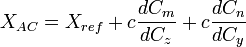
- .

- .

The Static Margin can then be used to quantify the AC:

where:
- Cn = yawing moment coefficient
- Cm = pitching moment coefficient
- Cl = rolling moment coefficient
- Cx = X-force ~= Drag
- Cy = Y-force ~= Side Force
- Cz = Z-force ~= Lift
- ref = reference point (about which moments were taken)
- c = reference length
- S = reference area
- q = dynamic pressure
- α = angle of attack
- β = sideslip angle
SM = Static Margin
References
- ^ Benson, Tom (2006). "Aerodynamic Center (ac)". The Beginner's Guide to Aeronautics. NASA Glenn Research Center. Retrieved on 2006-04-01.
- ^ Preston, Ray (2006). "Aerodynamic Center". Aerodynamics Text. Selkirk College. Retrieved on 2006-04-01.
See also
- Aircraft flight mechanics
- Center of pressure
- Flight dynamics
- Longitudinal static stability
- Thin-airfoil theory
- Joukowsky transform
Torque-induced (gyroscopic precession)
Torque-induced precession (gyroscopic precession) is the phenomenon in which the axis of a spinning object (e.g. a part of a gyroscope) "wobbles" when a torque is applied to it. The phenomenon is commonly seen in a spinning toy top, but all rotating objects can undergo precession. If the speed of the rotation and the magnitude of the torque are constant the axis will describe a cone, its movement at any instant being at right angles to the direction of the torque. In the case of a toy top, if the axis is not perfectly vertical the torque is applied by the force of gravity tending to tip it over.

The response of a rotating system to an applied torque. When the device swivels, and some roll is added, the wheel tends to pitch.
The device depicted here is gimbal mounted. From inside to outside there are three axes of rotation: the hub of the wheel, the gimbal axis and the vertical pivot.
To distinguish between the two horizontal axes, rotation around the wheel hub will be called 'rolling', and rotation around the gimbal axis will be called 'pitching.' Rotation around the pivot axis is called 'spinning'.
First, imagine that the device is spinning around the pivot axis. Then some rotation around the wheelhub is added. Imagine the gimbal axis to be locked, so that the wheel cannot pitch. The gimbal axis has sensors, that measure whether there is a torque around the gimbal axis.
In the picture, a section of the wheel has been named 'dm1'. When the rolling starts, section dm1 is at the perimeter of the spinning motion. Section dm1 has a lot of velocity and as it is forced closer to the center of rotation, it tends to move in the direction of the top-left arrow in the diagram (shown at 45o in the direction of rolling). Section dm2 of the wheel starts out at the center of rotation, and thus initially has zero velocity before the wheel is rolled. A force would be required to increase section dm2's velocity to the velocity at the perimeter of the pivot axis' plane. If that force is not provided then section dm2's inertia will make it move in the direction of the top-right arrow. Note that both arrows point in the same direction.
The same reasoning applies for the bottom half of the wheel, but there the arrows point in the opposite direction to that of the top arrows. Combined over the entire wheel, there is a torque around the gimbal axis when some rolling is added to rotation around a vertical axis.
It is important to note that the torque around the gimbal axis arises without any delay; the response is instantaneous.
In the discussion above, the setup was kept unchanging by preventing rotation around the gimbal axis. In the case of a spinning top, when the spinning top is tilting, gravity exerts a torque. Instead of rolling over, the spinning top pitches. The pitching motion reorients the spinning top with respect to the torque that is being exerted. The result is that the torque exerted by gravity elicits gyroscopic precession rather than causing the spinning top to fall to its side.
Precession or gyroscopic considerations have an effect on bicycle performance at high speed. Precession is also the mechanism behind gyrocompasses.
Gyroscopic precession also plays a large role in the flight controls on helicopters. Since the driving force behind helicopters is the rotor disk (which rotates), gyroscopic precession comes into play. If the rotor disk is to be tilted forward (to gain forward velocity), its rotation requires that the downward net force on the blade be applied roughly 90 degrees (depending on blade configuration) before, or when the blade is to one side of the pilot and rotating forward.
To ensure the pilot's inputs are correct, the aircraft has corrective linkages which vary the blade pitch in advance of the blade's position relative to the swashplate. Although the swashplate moves in the intuitively correct direction, the blade pitch links are arranged to transmit the pitch in advance of the blade's position.
Torque effect
From Wikipedia, the free encyclopedia
The torque effect experienced in helicopters and single propeller-powered aircraft is a result of Isaac Newton's basic law of motion that "for every action there is an equal and opposite reaction"
In helicopters, the result of the torque effect is a tendency of the main rotor to want to turn the fuselage in the opposite direction from the rotor.
in a single-propeller plane, the result of the torque effect is a tendency of the plane to want to turn upwards and left in response to the propeller wanting to turn (bank) the plane in the opposite direction of the propeller spin.
Spiral slipstream
from wikipedia
Spiral slipstream (also known as spiraling slipstream, propwash in the US, or just slipstream in the UK) is a spiral-shaped slipstream formed behind a rotating propeller on an aircraft. The most noticeable effect resulting from the formation of a spiral slipstream is the tendency to yaw nose-left at low speed and full throttle. This effect is caused by the slipstream acting upon the tail fin of the aircraft: the slipstream causes the air to rotate around the forward-aft axis of the aircraft, and this air flow exerts a force on the tail fin, pushing it to the right. To counteract this, some aircraft have the front of the fin (vertical stabilizer) slightly offset from the centreline so as to provide an opposing force that cancels out the one produced by the slipstream, albeit only at one particular (usually cruising) speed, an example being the Hawker Hurricane fighter from World War II.It can also roll the aircraft to the right. This is also caused by the air hitting the fin of the aircraft. This effect is minimal (negligible).
Subscribe to:
Posts (Atom)